本記事ではFUSION360という三次元CADを使って3Dモデルを作成する方法を紹介します。
AUTODESK FUSION360 スケッチの編集方法
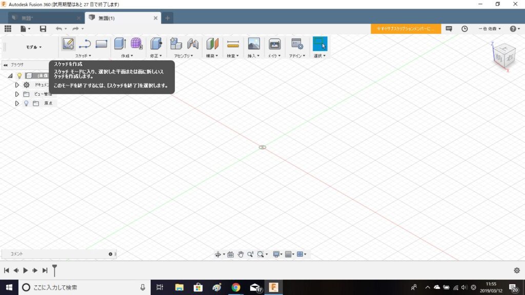
スケッチツールの「スケッチを作成」を選択すると、スケッチ平面を選択するように指示があります。
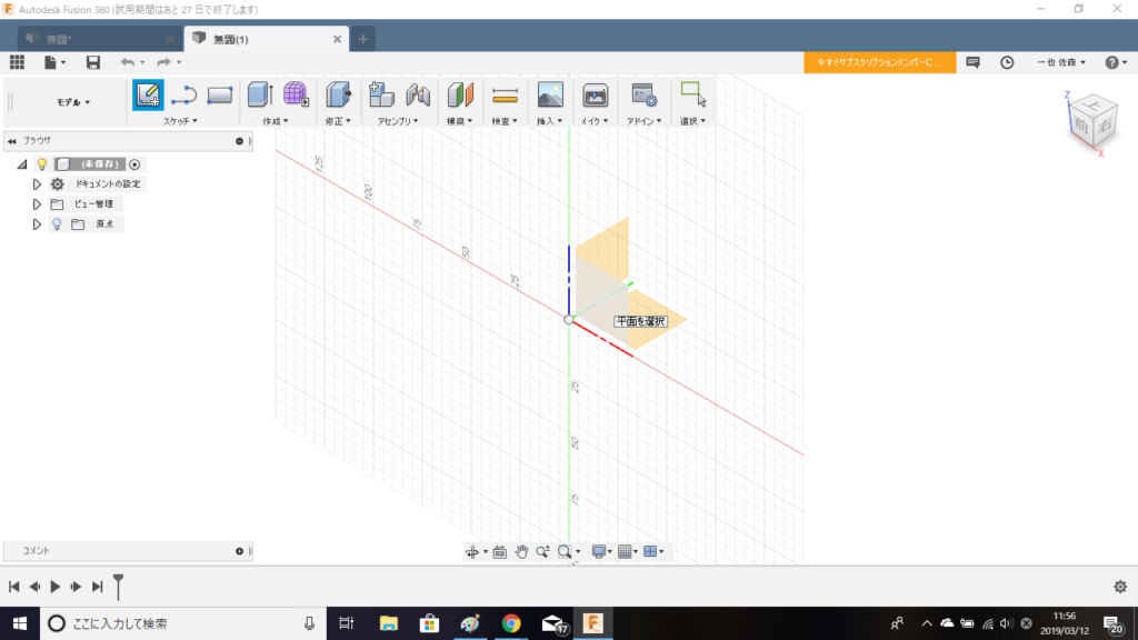
スケッチ平面を選択するときに、私は、基本的には「XZ平面」を選択するようにしています。「XZ平面」は正面図にあたるので、3Dモデルを作成する時にイメージしやすくなります。

スケッチツールの「線分」を指定します。
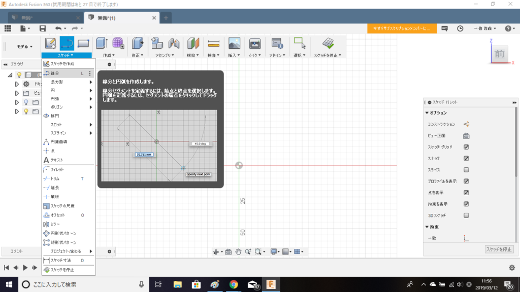
スケッチツールの「線分」を指定します。

「線分」を指定したら、適当にスケッチしていきます。
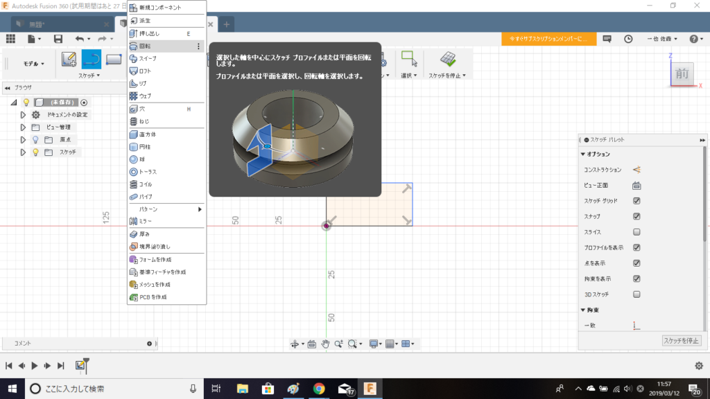
作成ツールの「回転」を使用して、3Dモデルを作成します。
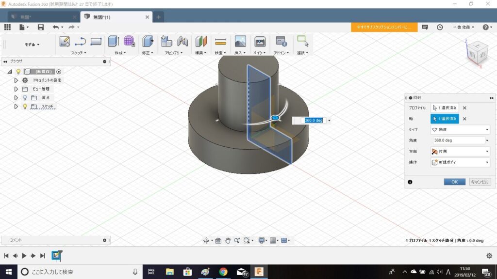
「プロファイル」と「軸」を選択したら、OKをクリックします。
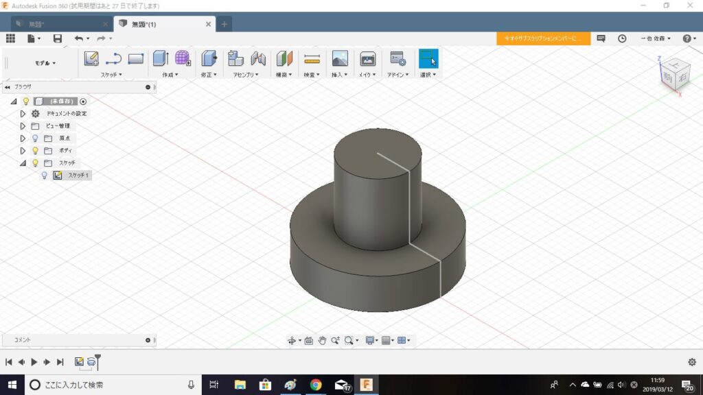
3Dモデルが完成しました。
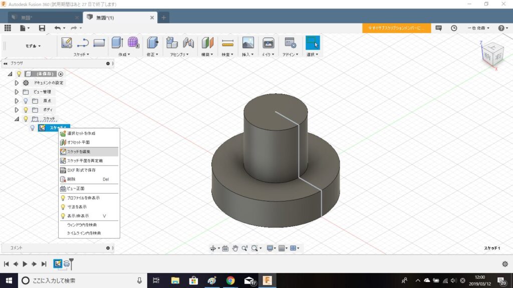
ツリーの中から、スケッチを編集を選択します。
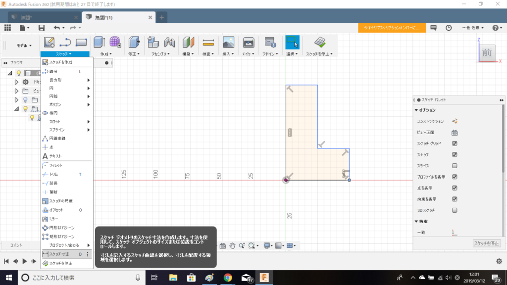
スケッチツールの中から「スケッチ寸法」を選択します。

寸法を編集したい線分二点を指定して、寸法を表示させます。
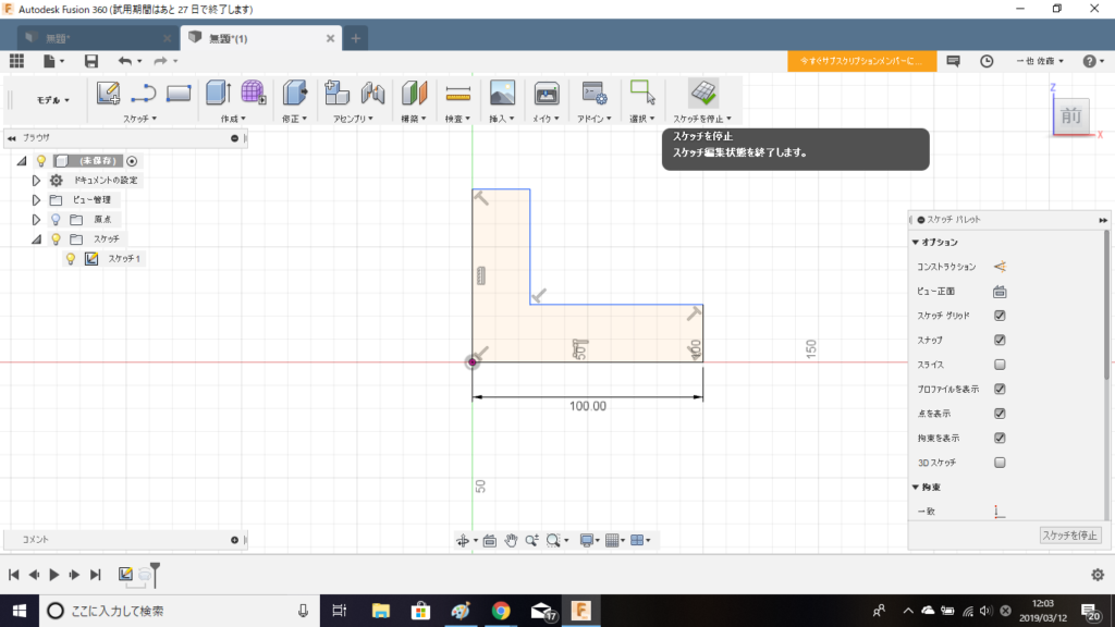
今回は、「50ミリ」から「100ミリ」に変更しました。
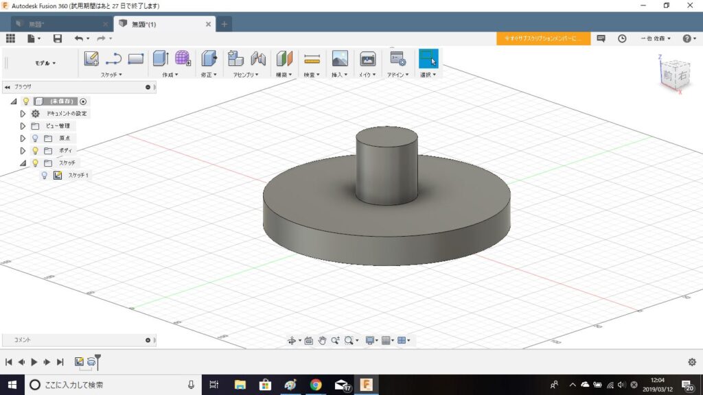
3Dモデルにも、しっかりと反映されています。
AUTODESK FUSION360 スケッチの編集方法まとめ
3Dモデルの作成方法についてはYouTubeに動画をアップしていますので宜しければ見てみてください。
コメント